Documentation index — full table of contents.
What you need
Material
-
Kyosho Mini-z Buggy MB-010 or Mini-z AWD MA-020 or Miniz RWD MR03 version MM (mid motor mount, we are missing a 3D printed part which is mounted in the back for the versions RM/HM/LM )
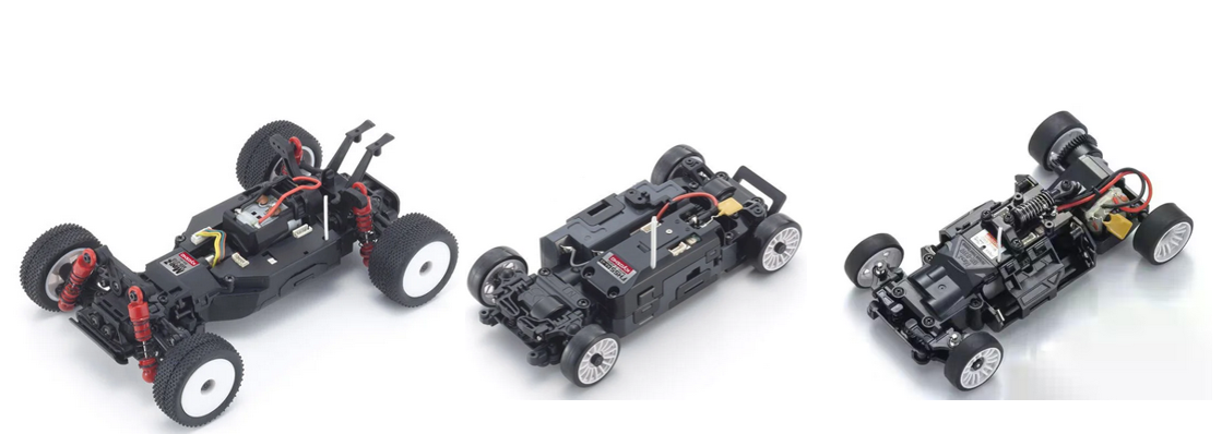
NOTE: we do not support any Kyosho model with a brushless motor. Only DC motors will work.
NOTE: if you want to use wheel encoders only the buggy is supported right now.
-
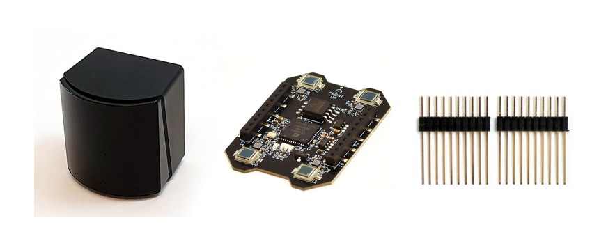
Bitcraze Lighthouse V2 base station + Lighthouse positioning deck + Male long deck connector ( + Crazyflie only used for flashing the Lighthouse deck. We are working on a solution so we don't need the Crazyflie)
-
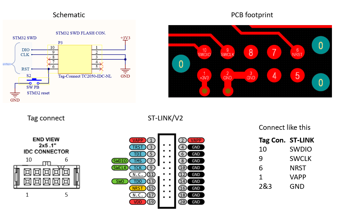
Programmers and lighthouse interface: https://www.digikey.ch/en/mylists/list/J5SZ37T4HD
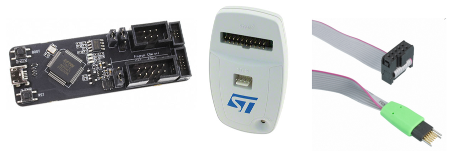
Note that the ST LINK and Tag-Connect need an adapter in between.
-
CRS ST Link adapter board: CRSProgramers.zip
- Batteries: 4xAAA we recommend the Panasonic BK-4HCDE/4BE since they are rechargeable and have a short circuit current of ~2A which is what we need when driving the cars.
- CRS PCB
- Gerber:CRS_RC_car_v20_with_PAP.zip
- BOM:Bill_of_Materials-CRS_RC_car_PCB_Project_Digikey.xlsx
- Shopping cart: https://www.digikey.ch/en/mylists/list/IW5FHFMQ9Z
- Schematic:Schematics_CRS_RC_car_v2.0.PDF
- Assembly drawing:Assembly_drawing_CRS__Car_v2.0.pdf
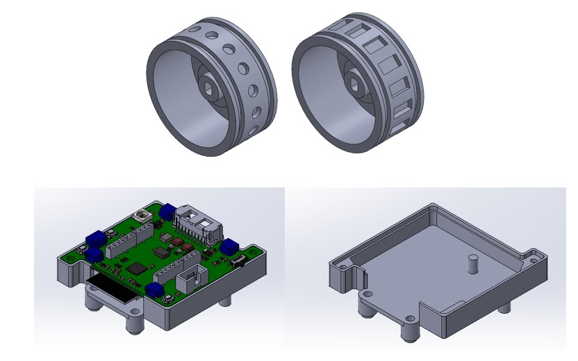
3D printed part
We recommend using a resin printer for the 3D printed parts.
Encoders
-
Buggy wheel encoder
- PCB
-
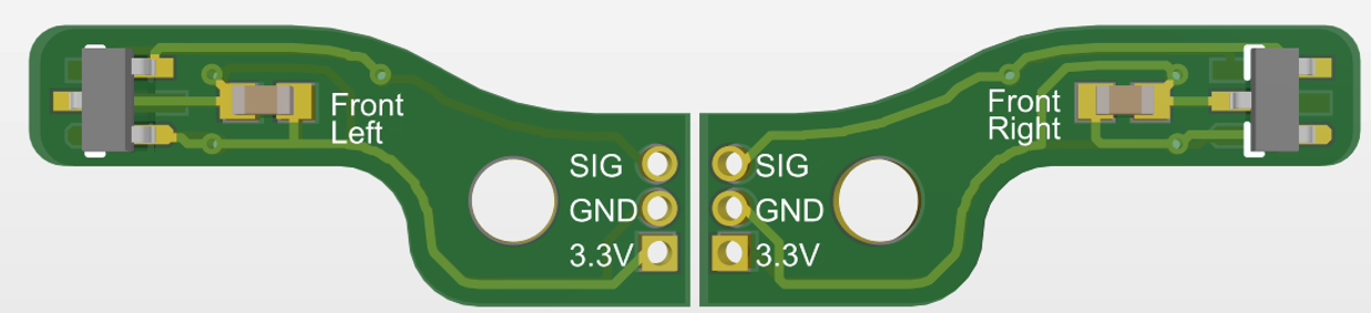
Front:
- Gerber:CRS encoder front PCB Project Outputs v1.zip
- Schematic:CRS encoder front v1.PDF
- BOM:Bill of Materials-CRS_RC_car_front_Encoder_Project.xlsx
- Shopping cart: https://www.digikey.ch/en/mylists/list/Y03682Z5GH
- Assembly drawing:Assembly drawing CRS buggy fonrt encoders.PDF
-
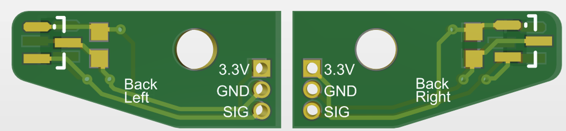
Back:
- Gerber:CRS encoder back PCB v1.zip
- Schematic:CRS encoder back v1.PDF
- BOM: Bill of Materials-CRS_RC_car_back_Encoder_Project.xlsx
- Shopping cart: https://www.digikey.ch/en/mylists/list/Y03682Z5GH
- Assembly drawing:Assembly drawing CRS buggy back encoders.PDF
-
Magnets:
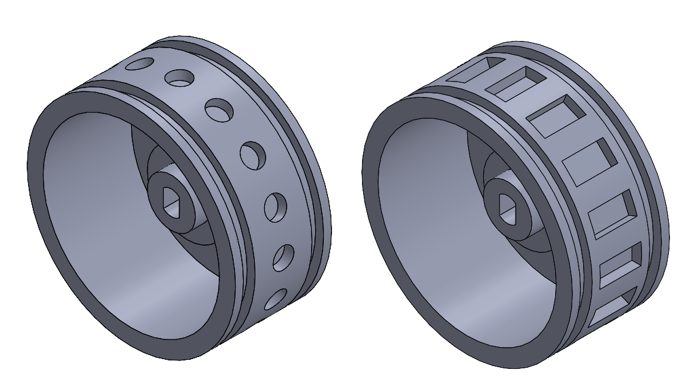
- Front: 16x Disc magnet Ø 2,5 mm, height 1 mm if you cant buy the round magnets we have a design which can hold square magnets in the front as well. The round just have less weight and performs as well as the square
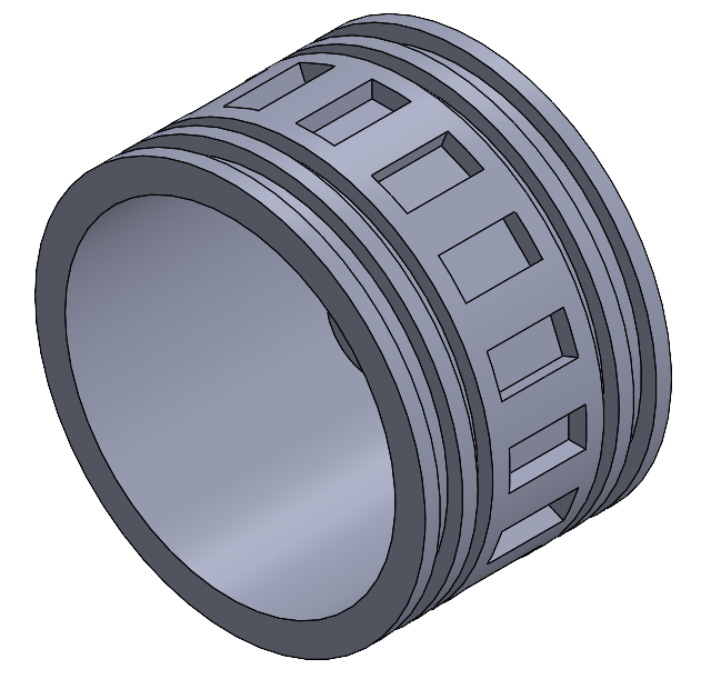
- Back: 16x Block magnet 5 x 2,5 x 1,5 mm NB: we tested with round magnets in the back but they did not perform as well as the square.
- Custom 3D printed wheels, we recommend using a SLA printer with an accuracy of ±0.2mm. We have tested the service from JLCPCB and that works great just select "SLA black resin":
-
Front:Magnet buggy front wheel - round magnet.STL or Magnet buggy front wheel 5x2.5.STL
-
Back:Magnet buggy back wheel 5x2.5.STL
Spare parts and optional upgrades
While performing test things might break, so it would be wise to keep the following spare parts at hand. We have also identified some optional upgrades which should help with the performance and keep your cars running a little bit longer.
Buggy:
- Original part: Mini-z Buggy MB-010 Front Knuckle MB006
- Original part: Mini-z Buggy MB-010 Kyosho Steering Plate MB008
- Original part: Mini-z Buggy MB-010 wheel nut MB009
AWD
- Original part: Mini-z AWD MA-020 Front Upper Bulk Cover Set MD203
- Original part: Mini-z AWD MA-020 Universal Swing Shaft MD008 and MD205 (front and rear)
- Original part: Mini-z AWD MA-020 Setting Tie Rod Set MDW003
- Original part: Mini-z AWD MA-020 wheel nut MD007
- Original part: Mini-z AWD MA-020 rear suspension
- Original part: Mini-z AWD MA-020 front suspension
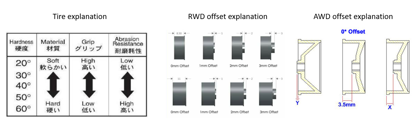
- Original part: Mini-z AWD MA-020 high grip tires. Note that the front (8.5mm) and back (11mm) has different width Front: MZW2-20/30/40/50/60. Back: MZW17-20/30/40/50/60
- Original part: Mini-z AWD MA-020 wheels. The wheels can be bought with different "offsets"
Other optional parts: http://kyosho.com/mini-z-info/products/optional-parts-for-mini-z-awd/
RWD
- Original part: Mini-z RWD MR03 rear suspension MZ403 (this is a set of spare parts for the suspension )
- There are four sub-models of the RWD, RM/HM and MM/LM. Basic difference between the models are how the motor in the back is mounted, which effects the length of the suspension arm.
- Upgrade: Mini-z RWD MR03 Carbon Rear Suspension Plate Set(RM/HM MZW404)
- Upgrade: Mini-z RWD MR03 Carbon Rear Suspension Plate Set(MM/LM MZW403)
- Original part: Mini-z RWD MR03 front suspension spring
- Original part: Mini-z RWD MR03 Servo Gear Set MZ404
- Original part: Mini-z RWD MR03 Front Knuckle MZ403
- Upgrade: Note that Kyosho don't supply and upgrade version of this part but there are a lot of other third party suppliers like this one
- Original part: Mini-z RWD MR03 wheel nut MZ203B
- Original part: Mini-z RWD MR03 high grip tires. Note that the front (8.5mm) and back (11mm) has different width Front: MZW2-20/30/40/50/60. Back: MZW17-20/30/40/50/60
- Original part: Mini-z RWD MR03 wheels. The wheels can be bought with different "offsets"
Other optional parts: http://kyosho.com/mini-z-info/products/optional-parts-for-mini-z-racer/
Tools
- Nut driver:3.5mm, 4.5mm, 5.5mm
- Phillips head screwdriver:#0, #1
- Hexagonal screwdriver:1.5mm
- Small metal file
- Solder iron
- PCB assembly equipment. The PCB need to be assembled which means this tools are needed:
- Stencil holder
- Reflow oven or similar
- Tweezers
- Microscope
Optional tools
- Metal thread insert tool like HELICOIL®. We use this so we can screw in standard metric sized bolts into the car chassis
Assembly guide
If a part of the guide is missing, don't worry, its coming soon!
Lighthouse deck
We communicate between the Lighthouse deck and the CRS PCB via the same connector as we flash the ESP32, 6 pin "PROG" socket. Make sure to flash your deck before assembling it.
Flash the deck
The firmware version we have tested is number 6
With a Crazyflie
- Installing the CFClient GUI or install from source
- Place the Lighthouse deck on the crazyflie and connect to it via a micro USB cable
- Start CFClient
-
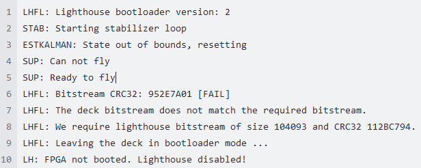
The console output before flashing should look like this:
-
how to flash lighthouse deck.zip (video)
-
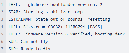
The console output after flashing should look like this:
Extra Notes
- The flashing from Cold boot (recovery) part is optional. It’s only needed if the crazyflie’s firmware is unknown and outdated.
- During the flashing, the “Status” label might show “Identifying deck to be updated” and might be stuck there for a long time.
- If it’s stuck for more than 1 minute, it might be because the drone is calibrating the IMU. Try holding it up and help it move in all directions and orientations. The drone should blink and emit a sound when that’s done. After that, the deck flashing should continue.
- It’s also fine to unplug/power-off the drone and repeat the whole flashing process, if the step is stuck for more than 3 minutes. The
cfclientGUI might need to be re-started, too.
Via the CRS PCB
TBD
Assembly
RC cars
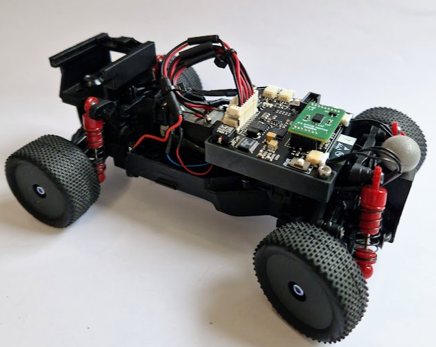
Mini-z Buggy MB-010
Encoders
PCB + cable:
-
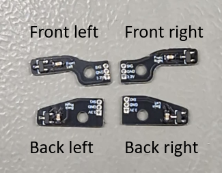
Populate the PCBs with the capacitor and hall sensor. Note the side to populate on!
-
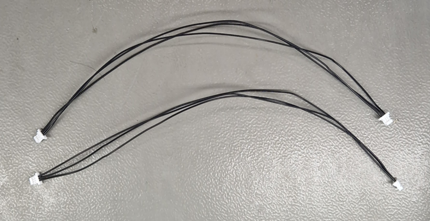
Assemble the connector (JST SHR-03V-S-B) with the pre-crimped wire (JUMPER SSH-003T-P0.2-H X2 12") as shown below. Note that how you connect the wires don't matter in this step.
-
Cut one side to 122mm (incl the connector) and the rest can be cut down to 80mm.
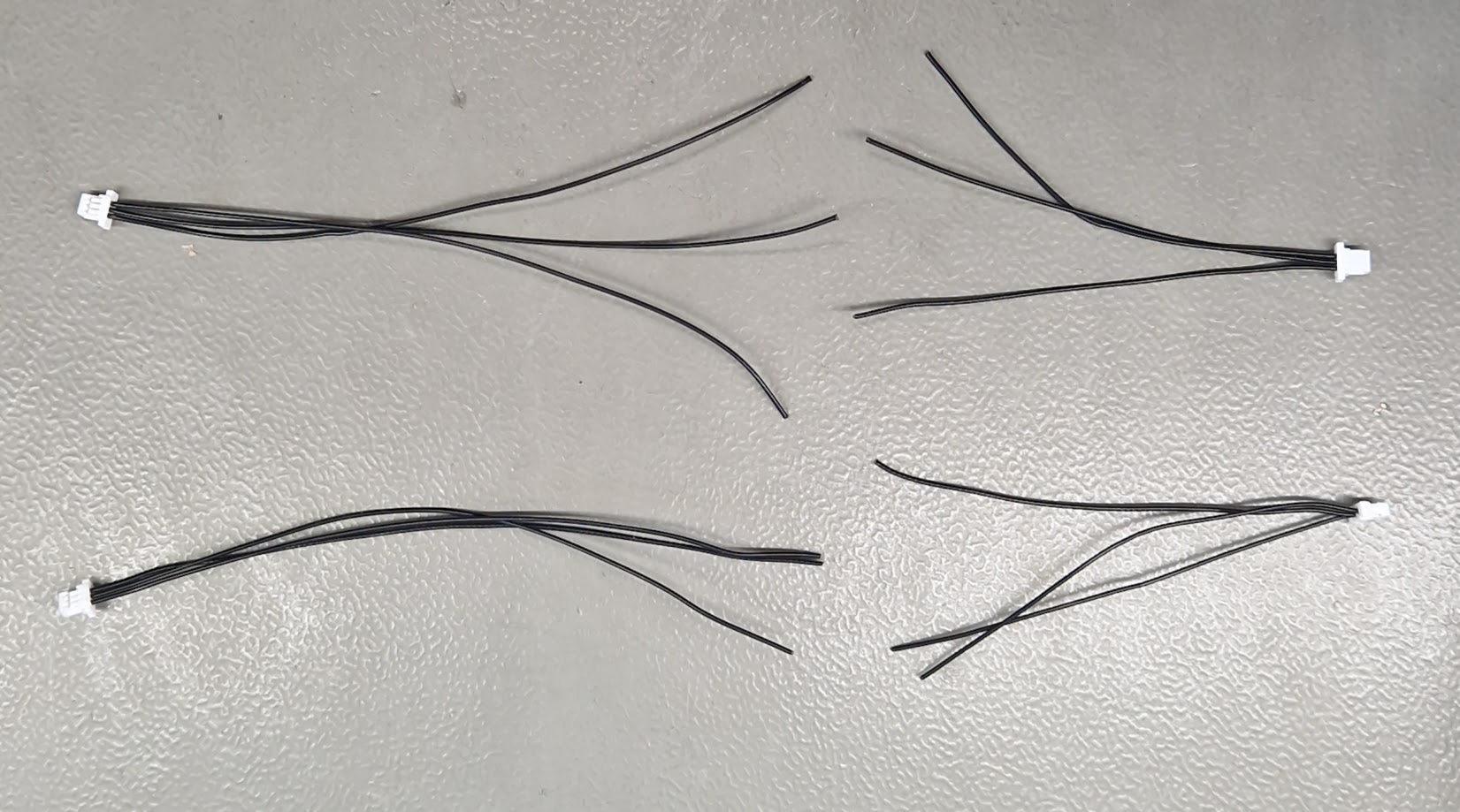
-
Solder the wires to the encoder PCB. Below is the pinout of the cable, the 80mm version is used in the front and the 122mm in the back.
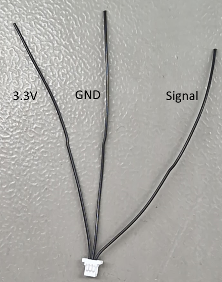
-
Pleas take note on which side the cables should be attached to the PCB.
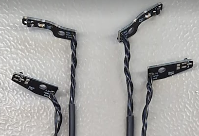
-
Last step is to add heat shrink which helps with our cable management and directs the cable out of the way from the car chassis
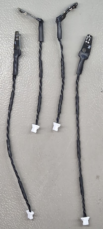
Wheels + magnets:
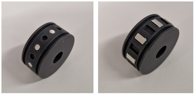
We found that super glue is the best adhesion to attach the magnets to the 3D printed wheels. We also recommend to use a rubber band to hold the glued magnets in place while it dry.
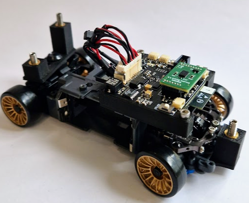
Mini-z AWD MA-020
-
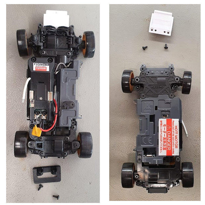
Start with removing the back and front (front is optional) bumper and replace them with "Mini-z AWD MA-020 rear bottom bracket" and "Mini z AWD ball bracket front M4" (optional)
-
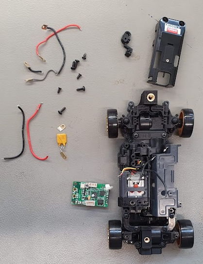
Next remove the plastic top cover, PCB, motor fuse (the yellow part mounted to the motor) and battery cables
-
Solder the CLIK-MATE wire (2157111121 and 2157112121) according to the wire schematic below. Note that the direction of both the drive and steer motor can be configure in software later if the wires are swapped around.
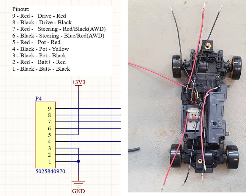
-
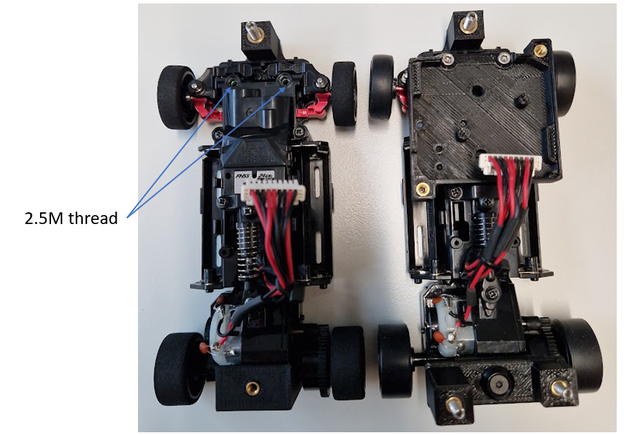
Connect the wires to the connector (5025780900) and attach the PCB to the "CRS PCB top bracket" which can be clued to the "Mini-z AWD MA-020 PCB bracket interface". Optional is to use a HELICOILM2 threaded insert or just thread directly into the plastic of the car.
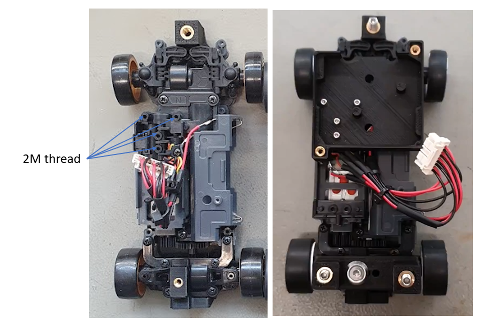
Miniz RWD MR03
-
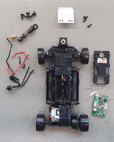
Remove the suspension, top cover, PCB, motor fuse (yellow part attached to the motor), battery cables and on/off switch.
(optional) Remove the front bumper and replace it with the 3D printed part "Mini z AWD ball bracket front M4" (same part for both RWD and AWD)
-
Solder the CLIK-MATE wire (2157111121 and 2157112121) according to the wire schematic below. Note that the direction of both the drive and steer motor can be configure in software later if the wires are swapped around.
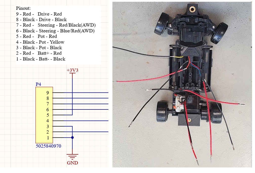
-
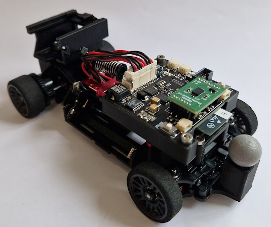
Screw back the suspension and connect the wires to the connector (5025780900) and attach the PCB to the "CRS PCB top bracket" which can be clued to the "Mini z RWD MR03 PCB bracket interface". Optional is to use a HELICOIL M2.5 threaded insert or just thread directly into the plastic of the car. Add the 3D printer part "Mini z RWD MR03 rear bottom bracket" in the back of the car.