Documentation index — full table of contents.
Overview
We have three different models of Wi-Fi enabled RC cars in the lab all of which are from Kyosho. All the models are using the same control PCB (named CRS RC Car PCB) and the same interface method with the RC car actuators.
Please read the Manual below on how to set up and use the cars.
Note that each time a PCB is placed on a new RC Car a re-calibration of the steering has to be made. If this is overlooked the car steering mechanism will be damaged!
Technical specification
Between the car models there are some parts which are being reused, drive motor, steering motor, steering gears, wheels, screws/nuts, battery model and differential which makes repairing and system identification easier.
The cars have also been slightly modified to account for the new control PCB and the Vicon markers.
Mini z Buggy 1:24
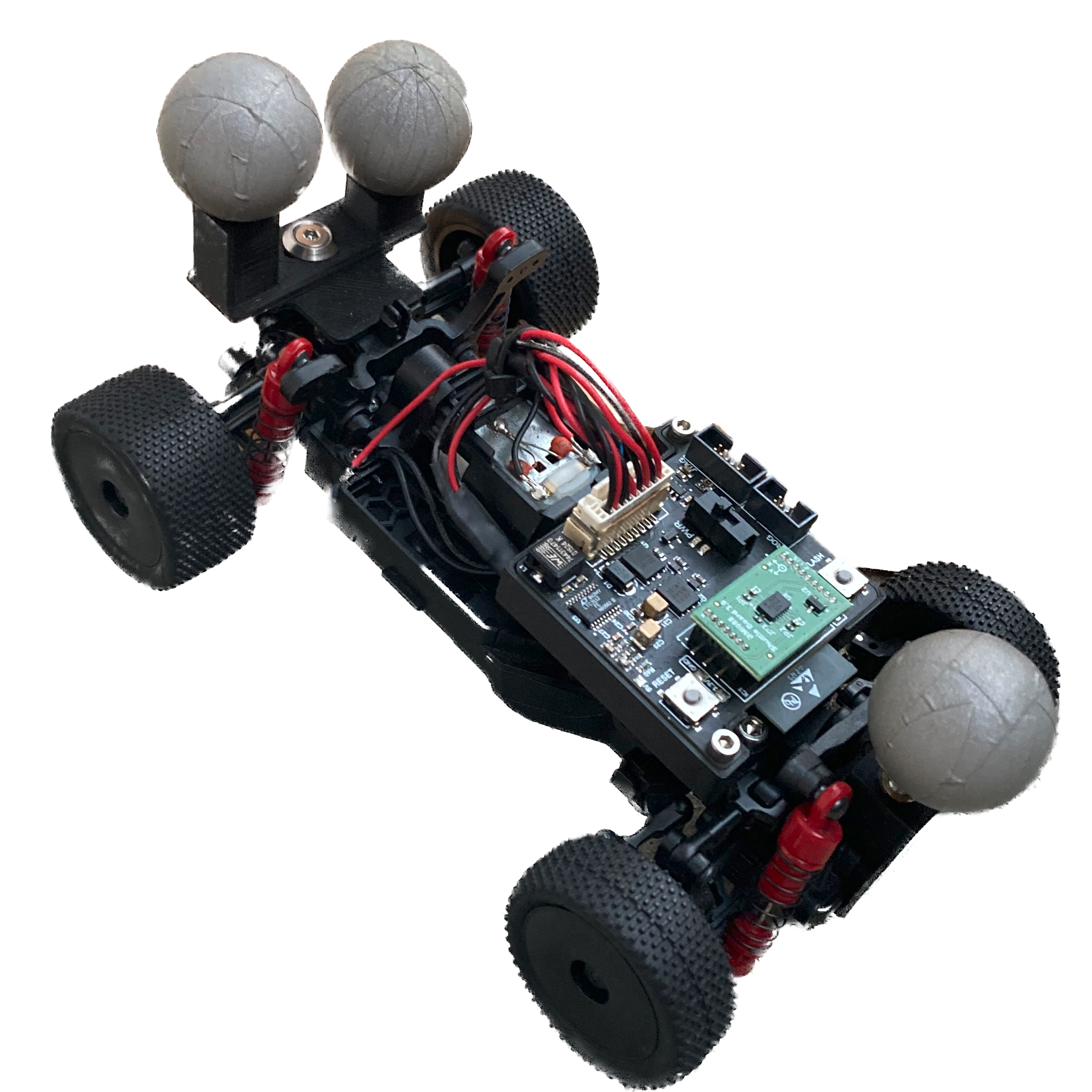
Length: 163 mm Width: 105 mm, height: TBD mm; trace (v) : 86.5 mm; trace (h) : 88.5 mm Wheelbase: 114.5 mm; Tires (v / h): Ø34, 7x16 mm Motor: 130s, Chassis Type: MB-010
Modifications
There are three modifications for the buggy, added wheel encoders (which only exist for the buggy model as of now), reflective marker bracket and helicoil screws for the PCB bracket.
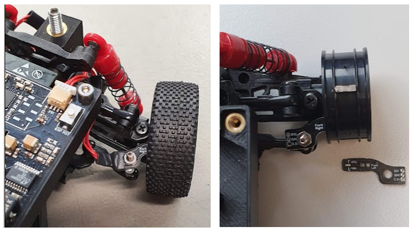
The front wheel encoders are mounted using an existing hole on the steering linkage arm where a threaded M2 screw has been added from the bottom. The custom make PCBs are secured with a nut.
The PCB bracket is mounted with two M2.5 screws.
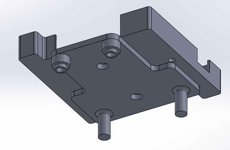
Remove the back wing, front and back bumper in order to add the reflective marker brackets, the new brackets mount too the existing holes of the car. 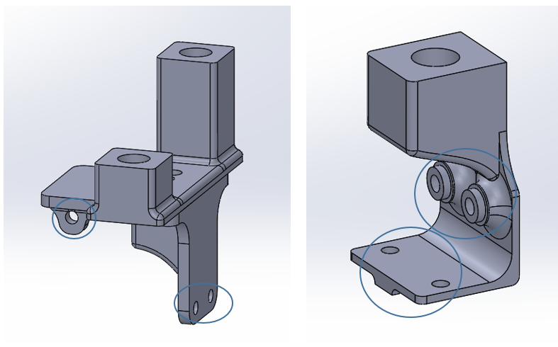
Mini-z AWD
Length: 127.5(M)-135.5mm(L) Width: 65-72mm Height: TBDmm Wheelbase:
90(M)-98(LL)mm Tread (F/R): 56.5-63.5mm / 56.5-61mm Tire(F/R):
25.0 (sold separately) Gear Ratio: 7.2, 6.4, 6.0, 5.7, 5.3, 5.0, 4.5 : 1
Motor: 130-class motor Chassis Type: Set 32150
Modifications
There are two modifications for the AWD, reflective marker bracket and helicoil screws for the PCB bracket.
The PCB bracket is mounted with four M2 screws.
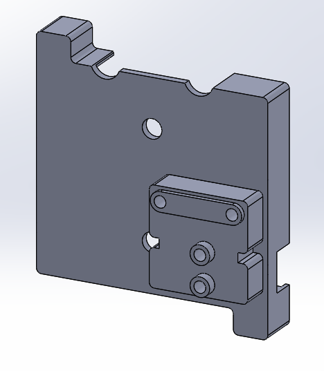
Remove the front and back bumper in order to add the reflective marker brackets, the new brackets mount too the existing holes of the car.
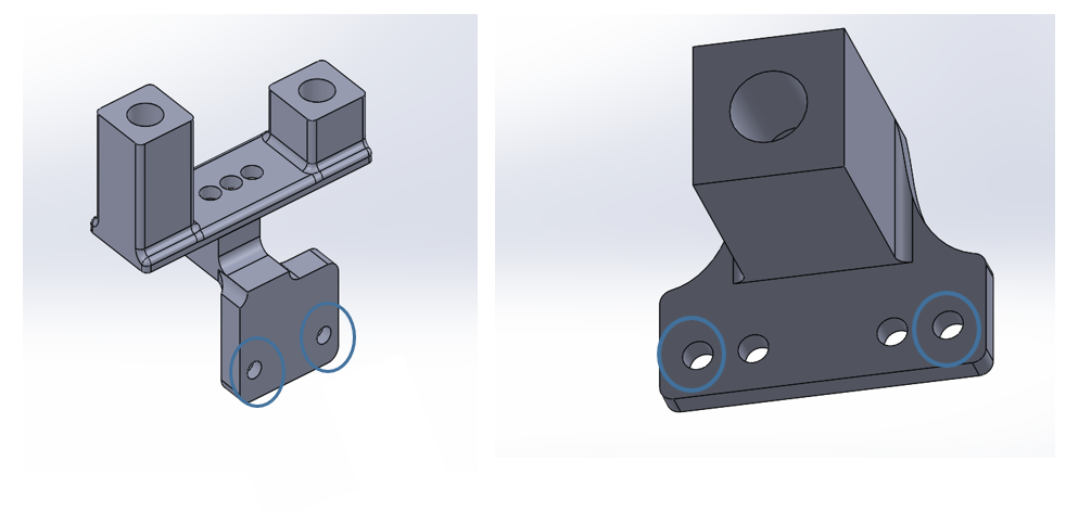
Mini-z RWD
Modifications
There are two modifications for the AWD, Vicon bracket and helicoil screws for the PCB bracket.
The PCB bracket is mounted with two M2.5 screws.
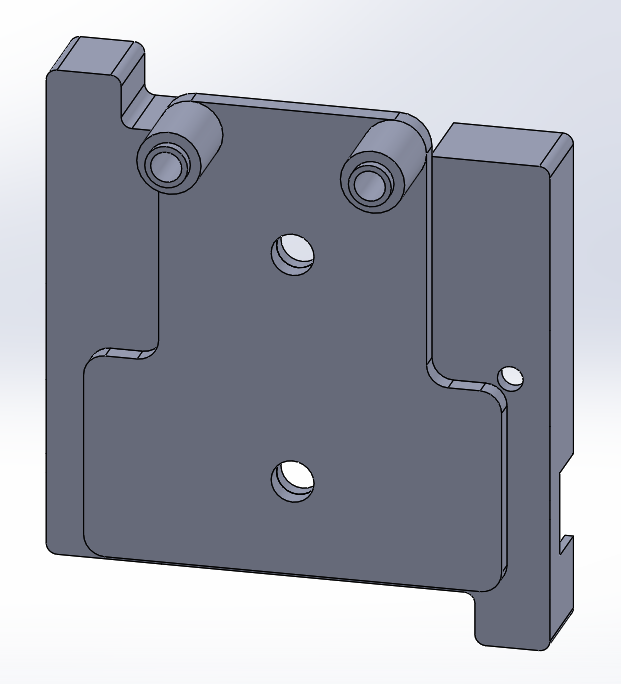
Remove the front and back bumper in order to add the reflective marker brackets, the new brackets mount too the existing holes of the car.
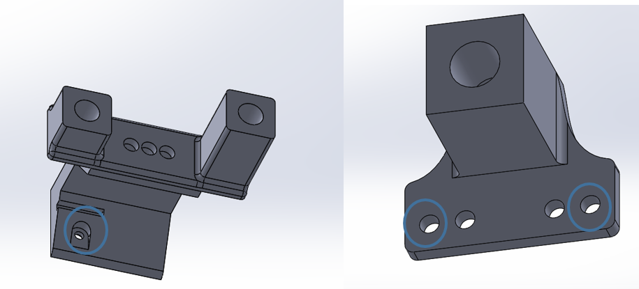
Spare part list
https://www.brack.ch/kyosho-kleinteile-set-mini-z-awd-924936
https://www.brack.ch/kyosho-kleinteile-set-front-suspension-arm-mini-z-mr-03-924947
https://www.brack.ch/kyosho-kleinteile-set-servo-gear-mini-z-mr-03-924946
https://www.brack.ch/kyosho-reifen-mini-z-radial-tire-set-30-1015974
https://www.brack.ch/kyosho-differenzial-mini-z-lm-1015976
https://www.brack.ch/kyosho-abtriebswellen-mini-z-4x4-1171622
https://www.brack.ch/kyosho-kleinteile-set-screw-mini-z-mr-03-924949
AWD Front upper cover
https://www.x24-shop.de/mpower-tuning/alu-front-upper-cover-ma-020-narrow-gunmetal
AWD Rear steering linkage
https://www.x24-shop.de/mini-z-zubehoer/awd-tuning/rear-steering-linkage-1-degree-blau-fuer-mini-z-awd
AWD Front Upper Arm Set
https://www.x24-shop.de/mpower-tuning/alu-front-upper-arm-set-ver.2-gunmetal
AWD original Front Upper Bulk Cover Set
https://www.x24-shop.de/mini-z-zubehoer/awd-ersatzteile/front-upper-bulk-cover-set-for-ma-020-md203
CRS RC Car PCB
Later version of the PCB: CRS_RC_Car_v.0.0P3
Overview of functions:
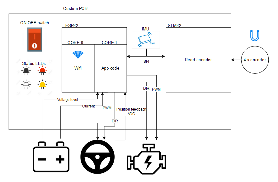
Technical specification:
Max input voltage: 15V, Reveres voltage input protection: yes, Under voltage protection: yes now configured at 4V since the min voltage for the batteries are 1V per cell.
Power consumption: switch in OFF position: 0,0432W, switch ON position: 0,7056W. If the actuators are not used, that will give us a an expect life time in idle of around 6h
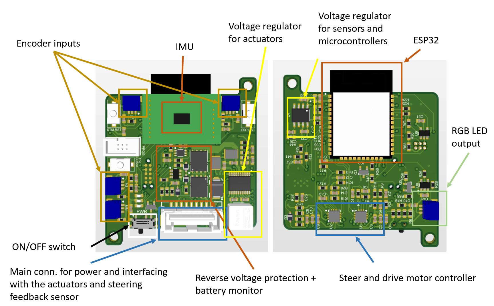
Voltage regulator for actuators
In order to future proof the RC car we opted for an buck/boost converter in the event that the battery topology might change. At the moment we are using 4xAAA battery's with a nominal voltage of 4-6V, If we later want to use a 1C or 2C lipo the circuit can handle it. Furthermore, by using a converter we can assure that the power supply for all the actuators will be keeps constant independent of the charge level of the battery.
Wheel encoder
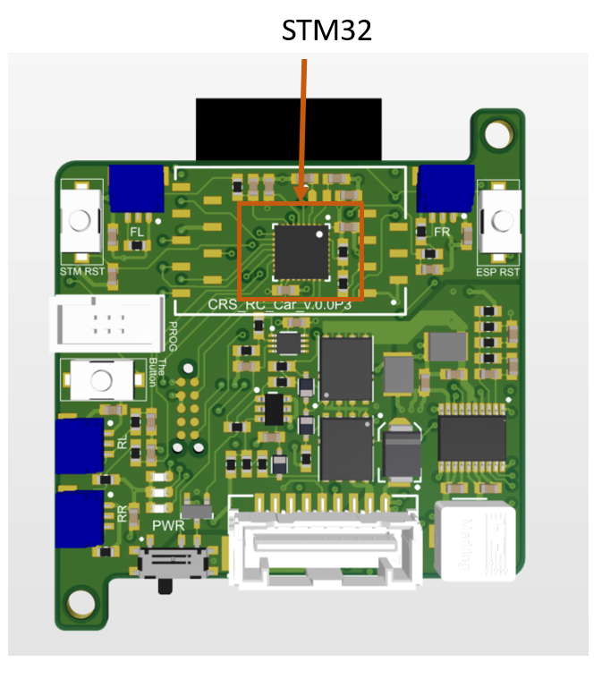
The STM32 is doing the work of reading the encoders from each of the wheels. The frequency is stored in a buffer which can be read out via SPI to the ESP32.
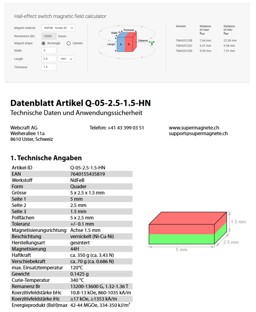
Inside each wheel two small magnet has been glued in place. Those magnets are then detected with a hall effect sensor that has been mounted on the inside of each tire rim.
The magnets has been selected for there size and magnetic strength using this tool to mach them with the appropriate sensor:
STM32
The STM32 is setup with four timers and four input capture interrupts, one for each wheel. Each timer is free running and with each interrupt we store the current counter. When we have captured two falling edges on one channel we can calculate the difference in time and get the current rotational speed.
The system clock is at 2.097MHz, the timers have a clock divider of 16 which means each count is 7,629947544us.
2.097MHz/16 = 131,0625kHz
We have a 16bit counter → 65536
1/131,0625kHz * 65536 = ~0.5 or 2Hz would be the lowest speed we could capture.
The difference is stored in a 16 bit value which then split up in two bytes and stored in a 8 byte arrary. The difference is the raw count value (0 → 65536 ) of the timer so the conversion to Hz or RPM need to be done elsewhere.
Front Right B[0]: MSB B[1]:LSB
Front Left B[2]: MSB B[3]:LSB
Back Right B[4]: MSB B[5]:LSB
Back Left B[6]: MSB B[7]:LSB
To get the value from the STM32 simply clock out 8x8 clock pulses. It dose not matter if there is data on the MOSI line.
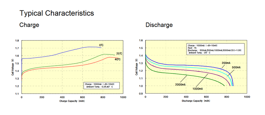
Battery model
This is the recommended model to use with the cars:
https://www.distrelec.ch/Web/Downloads/\\\\\\\\\\\\\\\\\\\\\\\\\\\\\\\_t/ds/Panasonic-ENELOOP%20P%204XAAA_eng_tds.pdf
Additional Resources
Further design information is maintained internally by the ICS group.
Handling and care
Manual
When using your car for the first time pleas follow the steps below in order not to damage the car or minimize any nuisance during operation.
Precondition:
Remove the battery from the RC car.
Initial setup:
- Inspect the car for damaged or debris:
- The most delicate part of the car is the steering mechanism.
with your hand carefully turn the wheels form right to left and make sure the steering arm is not blocked and attached to the motor. - Make sure the PCB is tightly attached to the bracket and that the bracket is attached to the car.
- Check that the reflective marker bracket and markers are all secure and not lose. This will corrupt your measurements if they are moving during operation.
- Check that each of the wheels are spinning freely. If one wheel has a higher spinning resistance the differential will transfer power to another wheel which will alter the dynamics of the car.
- Make sure the suspension is not blocked.
- The most delicate part of the car is the steering mechanism.
- Make sure that the intended batteries are fully charged.
- Have the latest firmware flash for your control PCB before using the car. See section "Flashing firmware onto the PCB"
- Make sure the power cable is connected to the PCB
Using the car:
- Connect the batteries to the car and follow the battery orientation written on each car model.
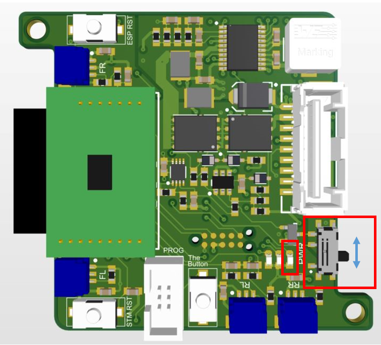
- Turn on the car by sliding the switch up, the "Power Good" LED will turn green.
- After 30 seconds connect the car's Wi-Fi (named crs-car) from your phone or computer.
- Open a browser and navigate to http://192.168.4.1/config. Make sure you use Safari or Firefox for the configuration.
- Make sure the car is sitting on the ground with nothing blocking the steering and push the "Trim Steering" button. This will reconfigure the range for this car, note that each car will have slight differences which means this is important to do each time a new car is setup or a PCB is moved between cars.
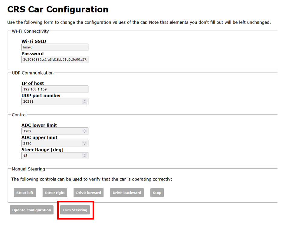
- After the calibration is done test the steering directions by pushing the Steer right and Left button. Note that the toque output for this test is small so a small push might be required to get it to move.
- Now test the drive motor with the Drive forwards and backwards button.
Flashing firmware onto the PCB
See the firmware section of the manual.
Troubleshooting
For any hardware issues, please open an issue on the CRS repository. Members of the ICS group should contact the hardware maintainer directly through the group's internal channels.