Rocket 6-DoF Model
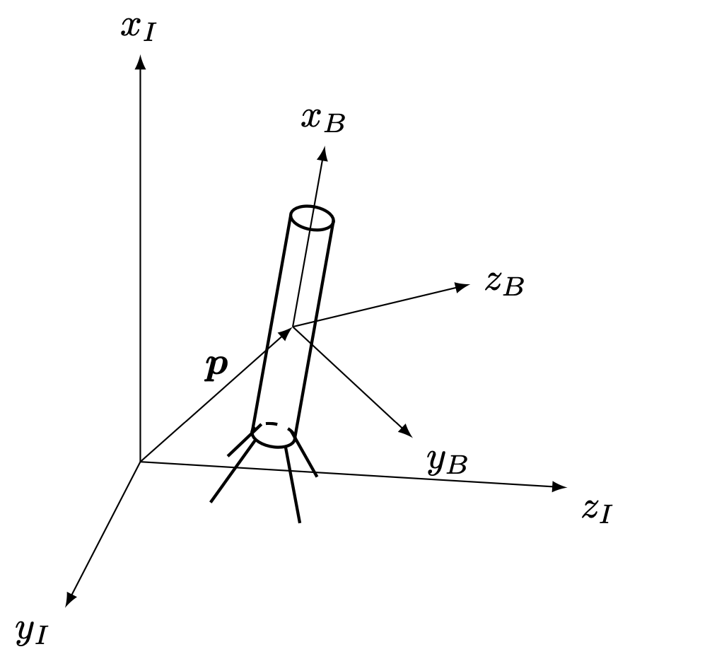
The rocket model used here is a simplified 6 DoF rigid body model as introduced in this paper. Quantities will either be expressed in the inertial frame \(\mathcal{F}_I\) (Up-East-North frame) or in the body-fixed frame \(\mathcal{F}_B\) whose x-axis points along the vertical axis of the rocket and the y- and z-axes pointing out the side of the rocket respectively. We use the following notation to denote a vector pointing from a to b in the inertial frame \(\mathcal{F}_I\): \({}_{I} \boldsymbol{r}_{ab}\).
Equations of Motion
with
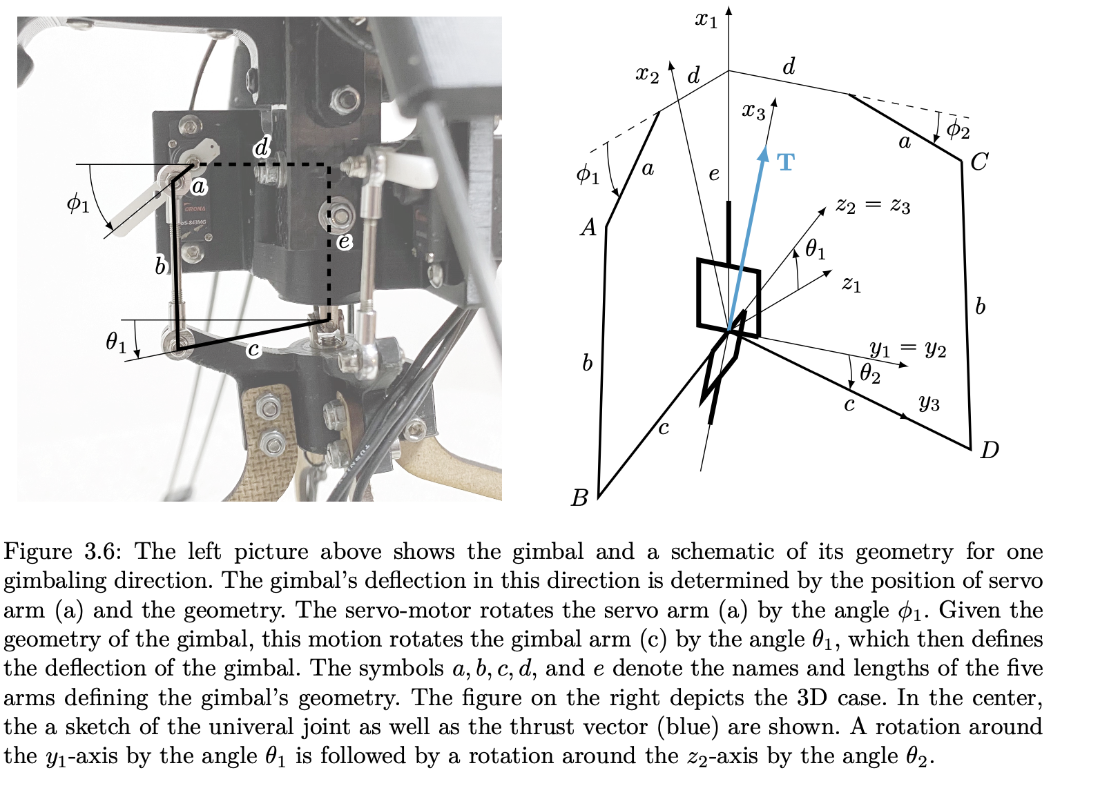
where the state of the system is given by \({\mathbf{x} = \left[{}_{I}\boldsymbol{p}^\top, {}_{I}\boldsymbol{v}^\top, \boldsymbol{q}_{IB}^\top, {}_{B}\boldsymbol{\omega}_{IB}^\top, F_x, T_x, \phi_1, \phi_2 \right]^\top}\). The symbols \({}_{I}\boldsymbol{p} \in \mathbb{R}^3\) and \({}_{I}\boldsymbol{v} \in \mathbb{R}^3\) are the position and velocity of the rocket in \(\mathcal{F}_I\), respectively. The quaternion \(\boldsymbol{q}_{IB} \in \mathbb{H}\) denotes the aircraft's attitude, i.e. the rotation transforming vectors in \(\mathcal{F}_B\) to vectors in \(\mathcal{F}_I\), while \({}_{B}\boldsymbol{\omega}_{IB} \in \mathbb{R}^3\) is the associated angular velocity of the body frame \(\mathcal{F}_B\) relative to the inertial frame \(\mathcal{F}_I\) expressed in \(\mathcal{F}_B\). The symbol \(F_x \in \mathbb{R}\) represents the thrust magnitude of the actuator in the gimbal frame and \(T_x \in \mathbb{R}\) is the differential torque caused by the rotor group which for simplicity is expressed in the body frame. \({}_{I}\mathbf{g} \in \mathbb{R}^3\) denotes the gravitational force. The differential equation of the quaternion is norm preserving, implying that \(\|\boldsymbol{q}\|=1\). The model's input is the desired thrust magnitude, the desired body x torque and the desired servo angles \(\mathbf{u} = \left[u_F,\, u_T,\, u_{\phi_1}, u_{\phi_2}\right]^\top \in \mathbb{R}^4\). To model the delay in response of the motors, the dynamics of the inputs are modeled as a first order systems with the corresponding time constants \(\tau_{(\cdot)}\). The rotation matrix \(R_{BG}(\phi_1, \phi_2)\) represents the forward kinematics of the gimbal and indicates the rotation of the gimbal with respect to the body frame. For more details, please refer to Lukas Spannagl's MT report.
Given a quaternion \(\boldsymbol{q}_{IB} = [q_w, q_x, q_y, q_z]^\top \in \mathbb{H}\), the rotation matrix \(\boldsymbol{R}_{IB} \in \mathbb{R}^{3\times 3}\) associated with said quaternion is defined as
NOTE: The equations as presented in the linked paper are wrong in the sense that what they call \(q_{\mathcal{B}/\mathcal{I}}\) is actually \(q_{IB}\) using our notation!! I am not sure if this is an actual error or just different naming conventions. The mistake cancels out in the paper since the matrix \(C_{\mathcal{B}/\mathcal{I}}\) is formulated correctly if we assume \(q_{\mathcal{B}/\mathcal{I}}\) is actually \(q_{IB}\). The dynamics are hence consistent but care should be taken if \(q_{IB}\) is used in the code (especially if Eigen is used and not their conversion matrix) since it does not represent \(Q_{BI}\) as could be assumed from the paper.
Finally, given an angular velocity \({}_{B}\boldsymbol{\omega}_{IB} \in \mathbb{R}^3\), we define the quaternion propagation matrix \(\boldsymbol{Q}\) as
The distance between the engine's hinge point (\(h\)) and the vehicle's center of gravity (c) is represented by \({}_{B}\boldsymbol{r}_{ch} = [-r_{ch},0,0]^\top \in \mathbb{R}^{3}\), while the inertia matrix in \(\mathcal{F}_B\) is denoted by \({}_{B}\boldsymbol{J} \in \mathbb{R}^{3\times 3}\) and assumed to be diagonal.
Example Configuration
A full description of the parameters can be found here.
# type describes what type of model we want to use / should be loaded
type: "rocket_6_dof_discrete"

# Q (process noise covariance matrix)
Q:
 value:
   [
     [4.2, 0, 0, 0, 0, 0, 0, 0, 0, 0, 0, 0, 0, 0, 0, 0],
     [0, 3.5, 0, 0, 0, 0, 0, 0, 0, 0, 0, 0, 0, 0, 0, 0],
     [0, 0, 3.5, 0, 0, 0, 0, 0, 0, 0, 0, 0, 0, 0, 0, 0],
     [0, 0, 0, 1.8, 0, 0, 0, 0, 0, 0, 0, 0, 0, 0, 0, 0],
     [0, 0, 0, 0, 1.6, 0, 0, 0, 0, 0, 0, 0, 0, 0, 0, 0],
     [0, 0, 0, 0, 0, 1.6, 0, 0, 0, 0, 0, 0, 0, 0, 0, 0],
     [0, 0, 0, 0, 0, 0, 20, 0, 0, 0, 0, 0, 0, 0, 0, 0],
     [0, 0, 0, 0, 0, 0, 0, 20, 0, 0, 0, 0, 0, 0, 0, 0],
     [0, 0, 0, 0, 0, 0, 0, 0, 20, 0, 0, 0, 0, 0, 0, 0],
     [0, 0, 0, 0, 0, 0, 0, 0, 0, 20, 0, 0, 0, 0, 0, 0],
     [0, 0, 0, 0, 0, 0, 0, 0, 0, 0, 0.01, 0, 0, 0, 0, 0],
     [0, 0, 0, 0, 0, 0, 0, 0, 0, 0, 0, 2.7, 0, 0, 0, 0],
     [0, 0, 0, 0, 0, 0, 0, 0, 0, 0, 0, 0, 2.7, 0, 0, 0],
     [0, 0, 0, 0, 0, 0, 0, 0, 0, 0, 0, 0, 0, 0.1, 0, 0],
     [0, 0, 0, 0, 0, 0, 0, 0, 0, 0, 0, 0, 0, 0, 0.1, 0],
     [0, 0, 0, 0, 0, 0, 0, 0, 0, 0, 0, 0, 0, 0, 0, 0.1],
   ]
 is_diag: false

model_params:
 mass: 1.16
 gravity_constant: 9.81
 inertia_xx: 0.00210
 inertia_yy: 0.10000
 inertia_zz: 0.10000
 thrust_cog_offset: 0.42000
 thrust_magnitude_time_constant: 0.06000
 servo_angle_time_constant: 0.10 #maybe even more

 # the length of the rod going to the gimbal [mm]
 gimbal_a: 5.0
 # Length of the rod which connects the servo to the gimbal [mm]
 gimbal_b: 35.2
 # Straight line distance between the joint connecting the servo-gimbal
 # rod to the gimbal and the center of the universal joint [mm]
 gimbal_c: 33.0
 # Distance between the universal joint and the rotation axis of the servo in the body yz-plane [mm]
 gimbal_d: 28.0
 # Distance along the body x-axis between the universal joint and the servo rotation axis [mm]
 gimbal_e: 35.2