Overview
CRS for cars on hardware
CRS can be used to control Kyosho Mini-Z RC cars on a racing track. The general setup can be seen in the figure below.
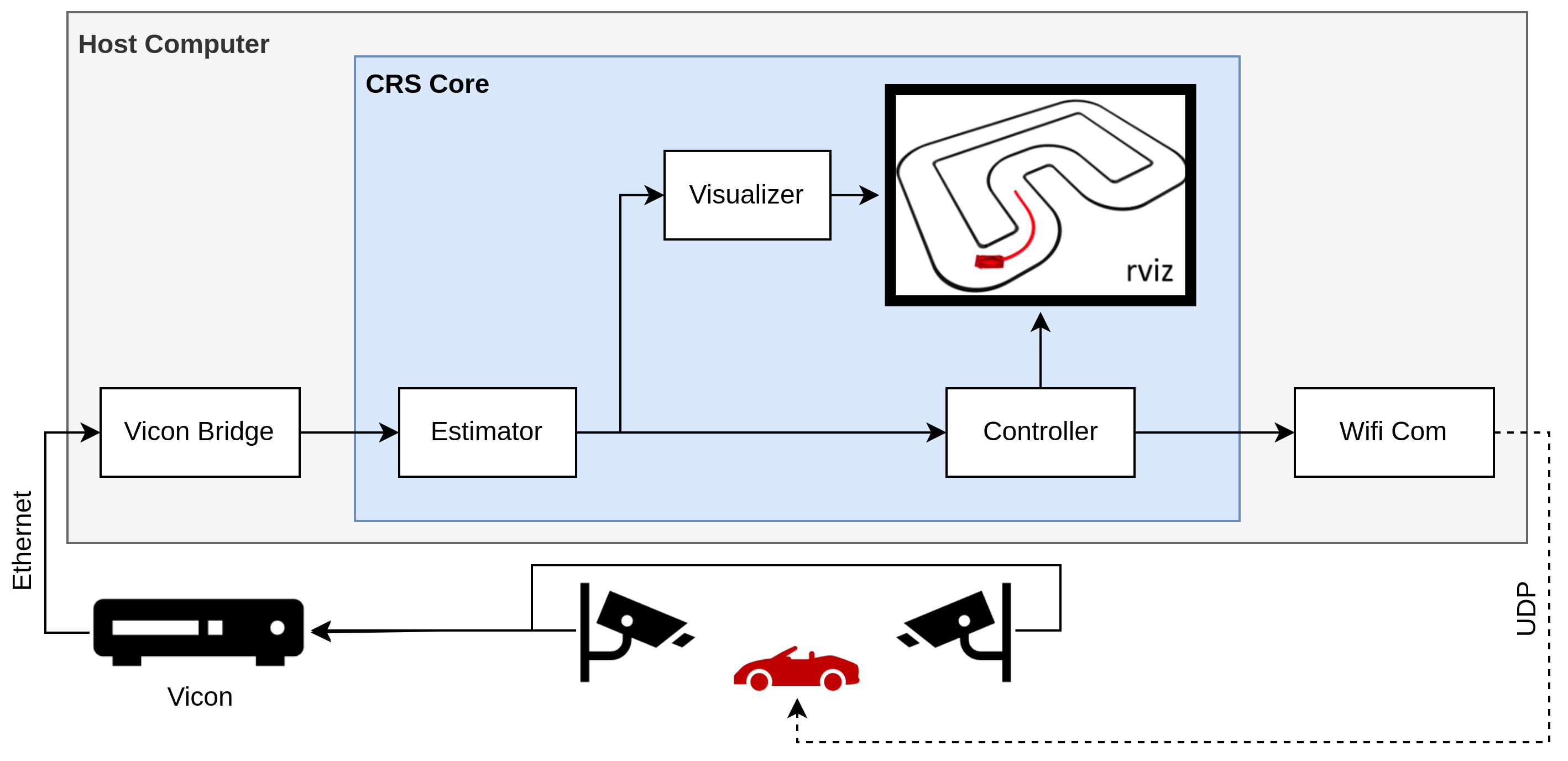
A computer where CRS is running is connected via Ethernet to the motion capture system. The motion capture systems is measuring the RC car’s position and orientation and sends this via Ethernet to the computer. The ROS node vicon_bridge or mocap_qualisys is handling this communication and publishes a message containing this information to ROS. When the Lighthouse system is used for localisation, the car position and orientation measurements are sent from the Wifi Com Node. For simplicity, in the next few paragraphs we will only refer to motion capture systems and not Lighthouse.
An estimator node subscribes to the motion capture measurements and computes the car’s state. The controller node subscribes to the estimate and publishes a suitable control input. At the same time, a visualizer node also subscribes to the state estimate and graphically depicts the car on the track via RViz.
The Wifi Com Node then handles the communication between ROS and the wifi module that is located on top of the car in order to provide steering inputs.
CRS for cars in simulation
To make software development easier and test controllers and estimators before deployment, this pipeline also exists purely in simulation.
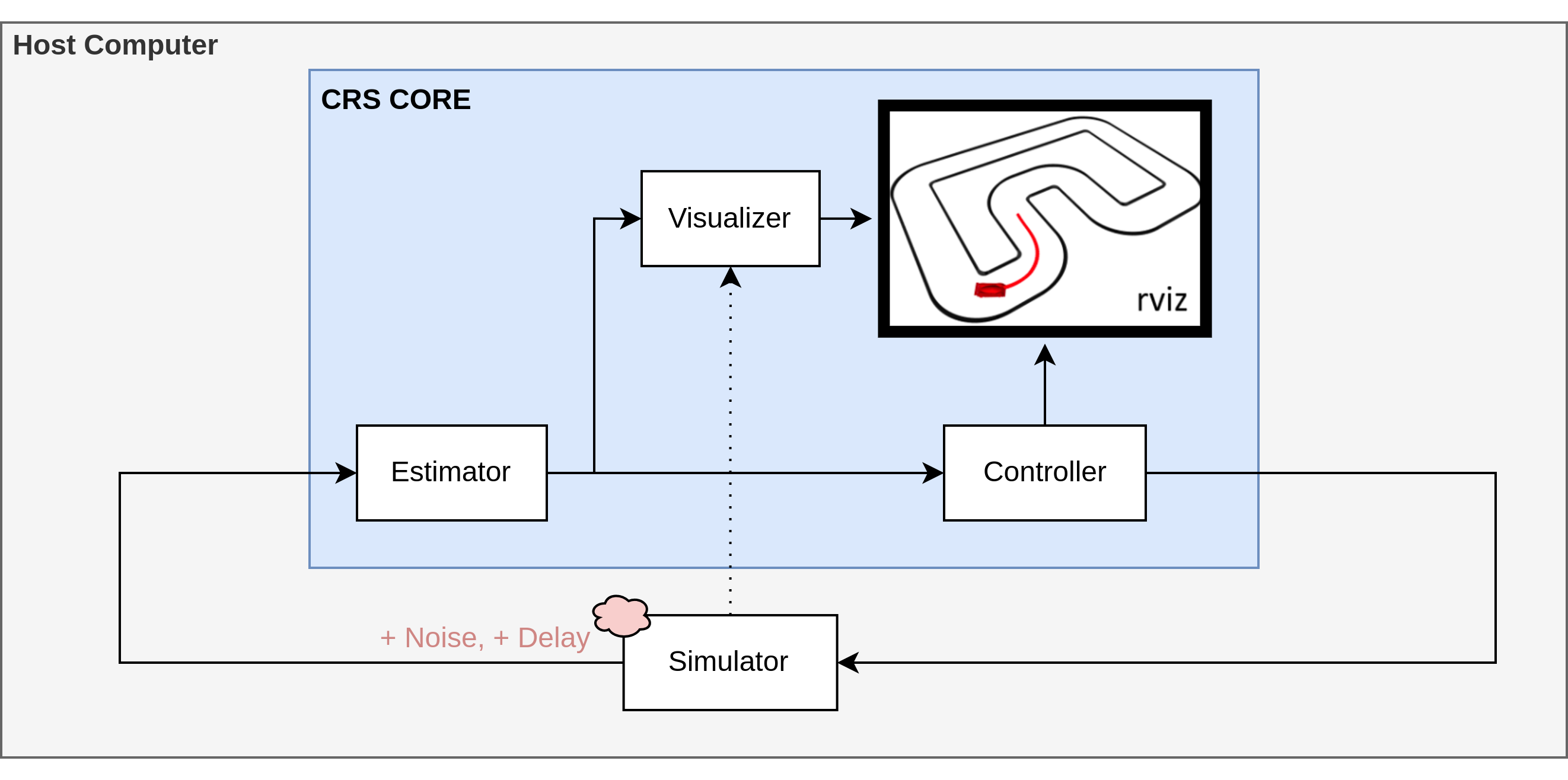
In this case, serial_com and vicon_bridge/mocap_qualisys are replaced by a [simulator node]/(ros-simulators), which simulates the vehicles behavior while executing the controller node’s commands. The controller and estimator nodes remain the same as if CRS were running on hardware. This makes deployment easy after everything is running fine in simulation.
To make simulation more realistic, the motion capture message published by the model can be perturbed by noise and delay. This can be used to test the controller’s robustness due to these effects. Additionally, we can make model-based controllers use different model parameters than the model to simulate model mismatch. Next to the motion capture message, the simulator node still publishes the unperturbed car state to give some ground truth. In simulation, the controller can also subscribe to this ground truth state message directly to take the estimator out of the loop.
This true state is also visualized by the visualizer node, which subscribes to the model instead of the estimator in simulation.
Using a collision backtracker
When tuning parameters in real world experiments, the car might drive into the car boundary and is not able to recover from this accident.
In order to overcome this issue, a collision detection and backtracking setup is integrated into the framework which allows to recover from an accident.
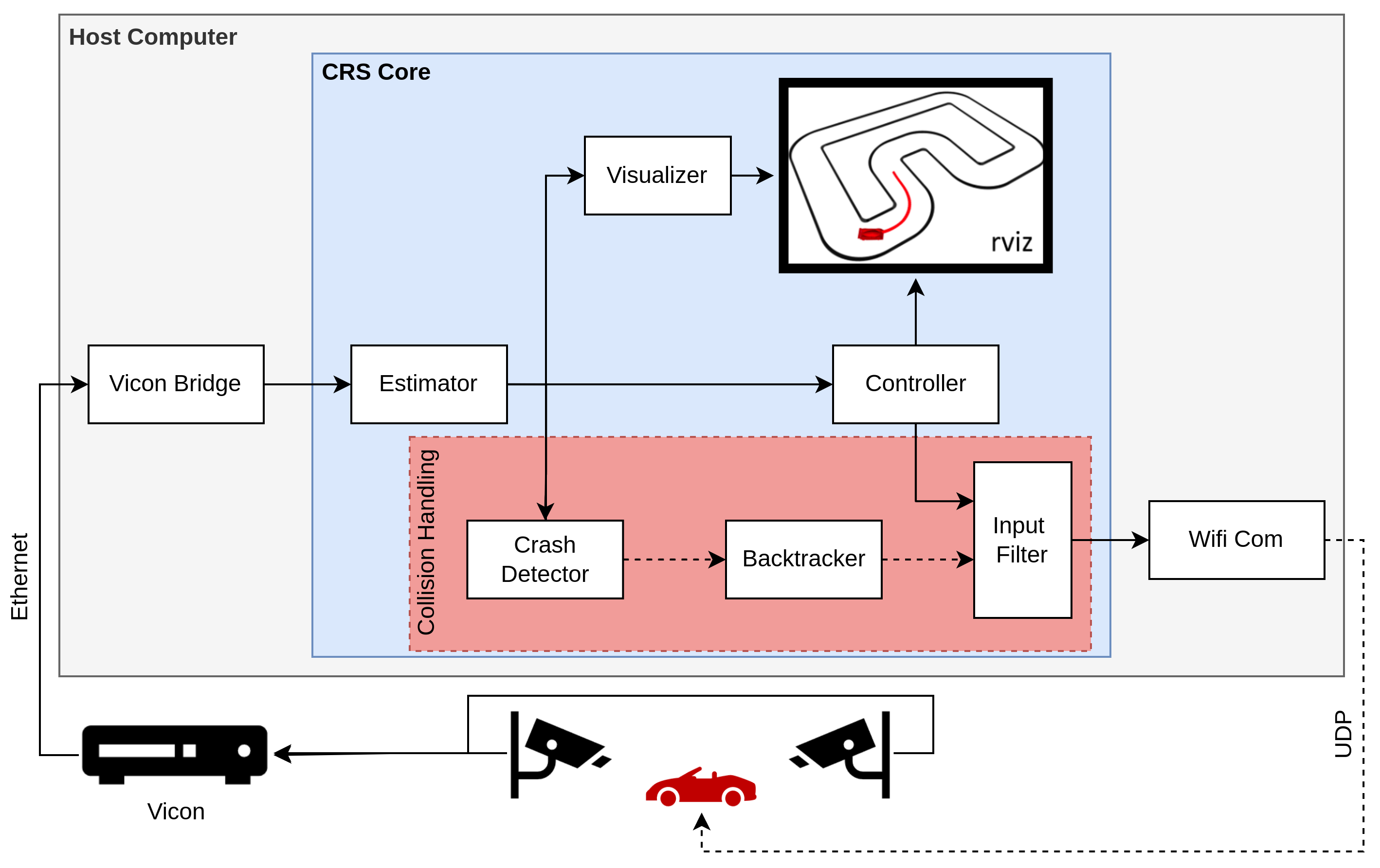
When using the collision recovery system, three additional components are loaded as described in the section Backtrackers. First, the collision detector node detects a collision based on some predefined criterions (min distance moved, offset from center line of the track). Once a collision is detected, the backtracker node is activated, which provides recovery inputs to the car. Finally, the input filter decides which control input to apply in order to bypass the control inputs from the controller.